
Segmented Hex Dies Design: What to Check Before Ordering
Segmented hex dies design should be reviewed as an assembly: the hex profile, segment joints, supporting case and acceptance method need to refer to the same approved drawing revision. Ordering a replacement from across-flats size alone leaves important interfaces undefined.
This guide helps fastener buyers prepare a drawing review and a comparable RFQ for cold heading tooling. It does not prescribe a segment count, interference fit or machine setting. Those decisions require the actual part, tooling and process data.
Identify the tool before comparing designs
A hexagonal finished head does not identify the tooling route by itself. Ask whether the requested tool forms the external head, forms an internal recess, or trims an already formed head. Mark the machine station and the contact surface on the assembly drawing. A hex punch insert and a hex die insert are different order items.
Japan Hardware's segmented-tool range distinguishes punch and die inserts and describes segmentation as a response to corner stress in its own designs. This supports checking the assembly type; it does not establish a universal tool-life benefit or a specification for Jungu tooling.
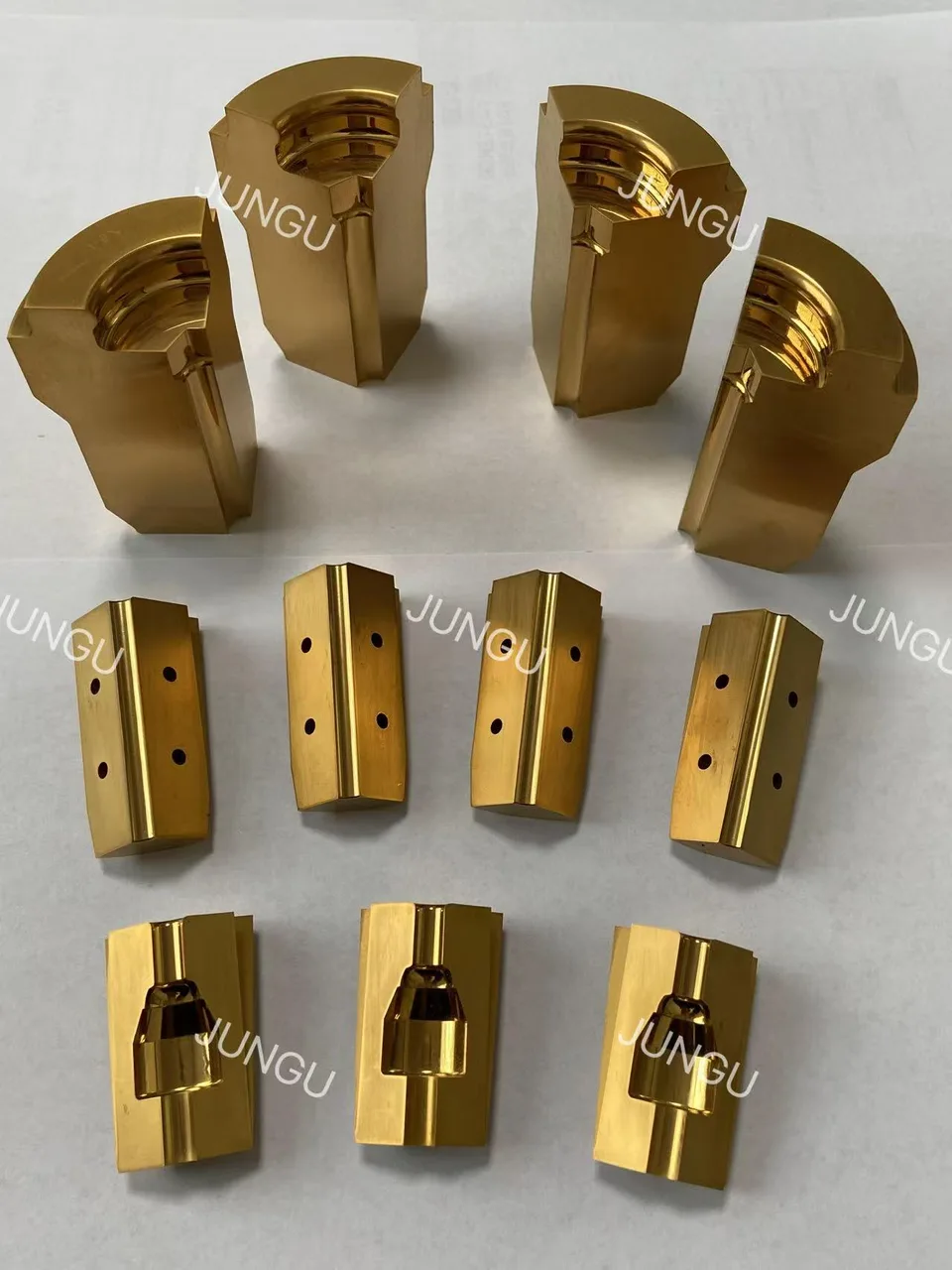
For a bolt-head application, see the tungsten carbide hex bolt die detail page. Use the broader segmented dies range to identify related tooling families before sending an enquiry.
Use a drawing register, not an unlabelled sample
Prepare three linked records: the finished-part drawing, the tool assembly drawing and the individual component drawings. Record a revision for each. If a trial introduces a changed corner, backing piece or case dimension, identify which other drawings must change with it.
A used sample helps show wear and assembly orientation, but it cannot settle the intended original dimensions. Label measurements taken from the sample separately from approved dimensions. Preserve the sample's position in the set and photograph it before cleaning or separating the components.
For example, “replace one damaged segment and retain the case” is an incomplete order unless the retained case and the remaining segments are identified. Ask the supplier to state which interfaces will be checked and whether a single-segment replacement can be accepted for that particular set.
Separate finished-part requirements from tool dimensions
| Review record | Information to agree |
|---|---|
| Finished hex profile | Across-flats requirement, head height, corners, chamfers and the applicable drawing or gauge. |
| Assembled cavity | Inspection condition, reference surfaces, segment orientation and cavity transitions. |
| Segment interfaces | Joint locations, identification marks and the specified contact or support surfaces. |
| Case and backing | Which components are new, which are retained, and which drawing defines their fit. |
| Process context | Machine, station, incoming preform, workpiece material and relevant operating documentation. |
| Acceptance evidence | Inspection report, labelled trial parts, agreed defect limits and the person responsible for approval. |
Do not copy a finished-head dimension directly into a tooling order without an engineering review. Instead, ask the tool designer to identify how the approved cavity relates to the required part and how both will be inspected. This article supplies no generic compensation allowance.
Clarify what “segmented” means in this assembly
Ask whether the segments remain constrained during the relevant operation or whether the assembly deliberately opens for release. Record the intended sequence on the assembly documentation. The word “split” alone does not define a moving mechanism or its timing.
If controlled opening and closing is part of the requirement, review the open-close dies for fastener cold forming product page. Do not assume that a static segmented insert can replace an opening assembly because the cavity has the same visible outline.
Keep this component review separate from the overall cold heading forming-sequence review. The latter establishes the station plan; this review defines what is being supplied and accepted within that plan.
Agree the replacement scope before selecting a material
TEMSA's header-die examples include modular carbide components and replaceable segments in its own systems. Replaceability is therefore a design-specific feature, not permission to mix segments from unrelated sets.
Request an explicit scope: complete assembly, matched segment set, individual component, or insert with an existing case retained. List the material and treatment requirements already approved. If an alternative is proposed, ask for the reason, the changed drawing references and the trial acceptance plan.
Compare quotations on the same scope. One quotation may include a new case and inspection of an assembled cavity while another covers loose segments only. A lower total cannot be interpreted meaningfully until those differences are resolved.
Make the sample-approval record usable for repeat orders
Before the trial, agree how the assembled tooling and formed parts will be identified. Include the relevant assembly revision, wire or preform batch, machine station and inspection method in the record. Note any process change during the trial instead of attributing every difference to the tool.
For a visible joint witness, corner defect or incomplete profile, retain photographs and measured parts. State the observed condition and the acceptance requirement separately. A photograph alone cannot determine whether the cause is a segment interface, incoming material, support condition or process adjustment.
For the repeat order, refer to the accepted revision and trial record rather than simply “same as last time.” Identify any components that will be reused and any work needed before their condition can be accepted.
Send an RFQ that defines the assembly
Send the finished-part drawing, assembly and component revisions, machine and station details, workpiece material, quantities and the new-versus-retained component list. Add failure photographs or rejected parts where relevant, with the supplier permitted to use them only for the agreed review.
Send Jungu your drawings for a segmented-die quotation review. Mark unresolved dimensions as questions. An approved drawing and a clear acceptance record give the supplier a more useful basis than an assumed standard tolerance or an unsupported tool-life target.
Frequently asked questions
Does a hex profile always require six segments?
No segment count is specified by the keyword or finished outline alone. Ask the tool designer to justify the proposed construction for the actual assembly and application.
Can a single damaged segment be replaced?
Confirm this for the identified set. Check the retained components, matching requirements and assembled inspection before accepting a single-part replacement.
Is an assembled cavity inspection enough to approve production?
It answers a tooling inspection question. The agreed trial must also establish whether the formed parts meet the specified requirements under the documented process conditions.