
Cold Heading Die Design: Start with the Forming Sequence
Cold heading die design should start with the forming sequence, not just the final cavity. A finished-part drawing describes the result. The tooling order must also explain the intermediate shapes, which operation creates each feature, and how the part reaches the next station.
For buyers of bolt and screw tooling, this distinction separates two very different enquiries: replacing a known tool in an established process, and developing tooling for a new part. The second needs a process proposal before the tool drawings can be treated as a complete manufacturing package.
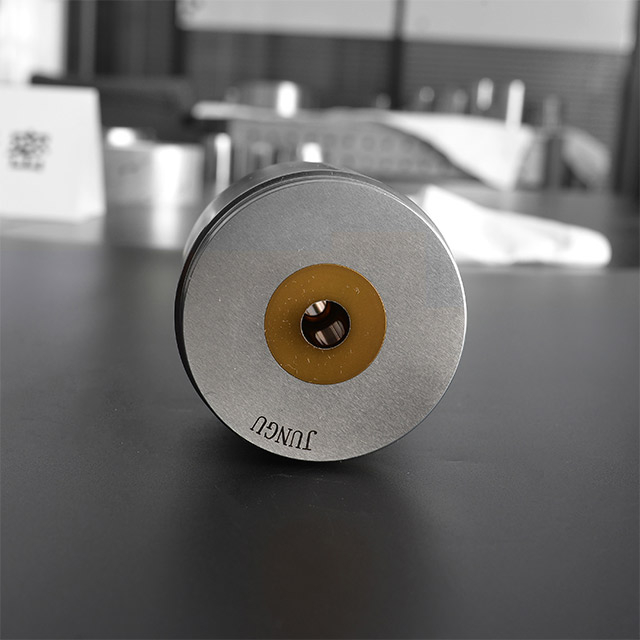
Define the part at the stage the header must deliver
Mark which dimensions apply directly after heading and which apply after thread rolling, machining, heat treatment or coating. A requirement on the finished component is not automatically a dimension to machine into the heading die.
Send both the finished drawing and, where available, the headed-blank drawing. Identify the revision, material specification, supplied wire condition and the operations that follow heading. If a headed-blank drawing does not exist, make its creation an explicit design deliverable.
For a repeat tool, include the current station drawing and tool identification. For a new development, ask for the proposed station layout. Do not label an unproven route as a replacement order simply because the final part resembles an existing screw.
Use blank volume as a first consistency check
A simple volume balance can expose a mismatch before detailed tooling work begins. For a cylindrical wire blank, V = πd2L/4. The geometric part volume can be assembled from cylinders and other defined features. State which stage and removed material the balance represents.
Illustrative geometry only: consider a solid, unthreaded shape consisting of a 6 mm diameter × 20 mm long shank and a 10 mm diameter × 3 mm thick cylindrical head. The lengths do not overlap. Ignore radii, chamfers and process allowances for this arithmetic example.
V = π/4 × (6² × 20 + 10² × 3) = 255π mm³
L = 4V/(π × 6²) = 28.33 mm
Thus 28.33 mm is the equivalent length of 6 mm wire in this idealized calculation. It is not a recommended cut-off setting. The actual model must include the real geometry, any trim or pierced-out material, and agreed allowances. The result does not establish formability, machine load or the number of blows.
Keep the calculation next to the drawing revision rather than as an isolated value in an email. If a head thickness changes, the volume check and affected process documents should be reviewed together.
Describe what each station changes
National Machinery's cold forming principles distinguish forward extrusion for diameter reduction, backward extrusion for hollow features, and upsetting for heads. Name the operation in the station proposal; “form to drawing” gives too little information.
| Review item | Ask to see in the station proposal |
|---|---|
| Incoming shape | Blank or preform drawing, orientation and revision entering this station. |
| Intended change | The feature being created or resized, with its intermediate target and inspection method. |
| Tool allocation | Which die, punch and associated components belong to this operation; identify supplied and retained items. |
| Outgoing shape | The next preform drawing and the surfaces used for locating, gripping and measurement. |
This is a review template, not a prescribed four-station route. List the actual station and blow numbers used by the proposed equipment. An intermediate shape needs its own identification even when it does not appear on the customer's finished-part drawing.
Do not turn forming rules into universal limits
In Dr. Vijay Nagpal's sequence-design article, workability, tool stress, machine capacity and transferability constrain the route. Unsupported stock can buckle during heading. This is why a general ratio or diameter-reduction rule cannot approve an unidentified process.
Ask the process designer to state the assumptions used for your material and machine. If the proposal needs another preform or station, request an explanation of the problem it addresses and the evidence expected from the trial. A lower tool count alone does not make two proposals equivalent.
Keep feasibility questions separate from promised tool life. A proposed geometry can still require development, and an accepted sample does not establish a guaranteed service interval.
Connect the sequence to the actual tooling assembly
Before ordering, request a marked assembly showing the die case, insert, backing and corresponding punch or ejector components where applicable. Cross-reference every supplied item to its drawing. Record what will be reused on the customer's machine.
The interface review should identify mounting dimensions, locating datums, fits and the relevant machine documentation. Leave engineering values to the approved design; a generic internet interference-fit figure is not a specification for a particular insert and case.
Also identify how the preform leaves the die and reaches the next station. Review ejection and transfer against the proposed intermediate shape. A complete final cavity drawing does not by itself answer those questions.
Make the design review produce inspectable evidence
National Machinery's process-development description lists simulation-based checks of flow, tooling stress, load, energy, fits and transferability. These are examples of feasibility work, not a claim that Jungu has simulated your part.
If analysis is proposed, request its inputs, scope and conclusions. For physical trials, agree which intermediate samples and final samples will be retained, which features will be measured, and who resolves a deviation. Review the measurements against the applicable stage drawing.
A useful release package contains the approved sequence, component drawings and revisions, assembly interfaces, inspection criteria and the trial report. Record open actions explicitly. “Samples look good” is too ambiguous to define what a repeat order must reproduce.
Prepare a cold heading tooling enquiry
Send Jungu the part and blank drawings, material and wire condition, machine model, available station information, and current tooling drawings if this is a replacement. State whether you need an individual die, a die assembly or a coordinated set with header punches and punch pins.
Browse our bolt and screw forming dies, or use the cold heading die supplier checklist to compare quotations. Send the drawing set for an enquiry and identify which process decisions are already approved and which still require development.
Frequently asked questions
Can a supplier design the die from the finished-part drawing alone?
It can be a starting point for discussion. The enquiry must still resolve the header output, process route, material and machine interfaces before detailed tools are released.
Does matching blank volume prove that the part can be cold headed?
No. It checks geometric consistency. Formability, tooling loads, support and handling require their own assessment.
Is changing the carbide grade enough to fix a design problem?
Do not assume so. Establish the process and assembly conditions first, then evaluate tool material in that context. For an existing damaged tool, use the separate cold heading die failure guide.