
How to Polish Carbide Dies Without Losing the Working Profile
To polish carbide dies, define the permitted working geometry first, assess the surface condition, select a suitable finishing route and verify the result by measurement. A bright cavity is not, by itself, evidence that its dimensions or working profile remain acceptable.
This guide explains how to review industrial carbide die polishing for cold heading tooling. It is a process and inspection overview, not a universal workshop recipe. Abrasive selection, tooling, machine settings and removal allowance must be approved for the actual insert and its starting condition.
Start with the difference between finish and form
Surface finish and form answer different questions. A surface requirement concerns the specified texture in a stated area. A form requirement concerns the cavity shape: its size, transitions, straight sections, radii or special profile. The inspection plan must address both where the drawing requires them.
For a used tool, compare the measured condition with the approved drawing before deciding what to remove. A worn cavity that is already beyond its permitted size cannot be brought back to that size simply by removing more material. That is a dimensional decision, even if the proposed operation is called polishing.
For a new insert, establish whether the previous operation has left enough controlled allowance for the planned finish. Ask which features must be preserved and which may change within the drawing limits. “Mirror finish everywhere” leaves that distinction unresolved.
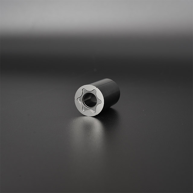
The custom carbide die core product page provides the relevant tooling context. Send the cavity and case drawings together when the insert is part of an existing assembly.
How diamond polishing fits into the process
CERATIZIT's carbide guide, printed pages 31–32, describes diamond-paste polishing, chosen according to initial roughness, and warns that coarse pastes can distort profiles and radii. That makes the intended geometry an input to the process, not something to check only after the surface looks good.
A useful process review separates preparation, any required geometry correction, the finish operation and final acceptance. Have the responsible toolmaker define each stage's objective and stopping point. Record whether the work is on a loose insert or an assembled tool, and identify surfaces that are outside the agreed scope.
Kemet's round wire-drawing-die procedure distinguishes rough lapping from finer finishing, includes cleaning between stages and ends with a size check. Its example is not a speed, abrasive-size or lap-shape specification for a cold heading cavity.
For a shaped insert, request a route that addresses the actual accessible surfaces. A round-bore example does not resolve how to preserve a lobed recess or a local transition. If those areas cannot be measured or protected as planned, resolve the method before processing the production tool.
Decide whether the job is polishing, rework or replacement
| Condition found | Decision to resolve |
|---|---|
| Surface marks with geometry still within the approved limits | Can a defined finishing operation meet the surface requirement without losing the remaining dimensional allowance? |
| A deep mark that would require substantial removal | Would removing the mark change a controlled dimension or transition? Review as dimensional rework. |
| Oversize, rounded or otherwise out-of-specification profile | Assess an approved redesign, another permitted application or replacement; a brighter surface does not restore the original geometry. |
| Suspected crack or chipped working edge | Hold the tool for an integrity and repairability assessment instead of concealing the evidence through cosmetic finishing. |
| Coated surface or unknown previous treatment | Identify the layer and agree the processing and acceptance route before changing it. |
These are review gates, not automatic repair approvals. Keep the original damage photographs and inspection results with the tool record. If repeated marks originate in the process, record the workpiece, lubrication and matching-tool evidence for the investigation as well.
A polished surface does not prove all prior damage is gone
CERATIZIT also cautions that polishing generally does not completely remove the zones affected by a previous EDM operation. Do not accept appearance as a substitute for an agreed manufacturing and integrity assessment.
For a crack indication, let the responsible specialist choose the assessment method and disposition. This guide does not recommend polishing through a crack or provide a universal depth that can safely be removed. For the wider investigation, use the cold heading die failure guide.
Inspect the same features before and after finishing
List the controlled features and reference surfaces on the drawing. Agree how each can be accessed and measured. If a surface-texture requirement applies inside a small or shaped cavity, confirm the measurement method before selecting a process; a single accessible flat surface may not represent the working area.
Use the same identified locations for the before-and-after comparison where practical. Record actual results, the method used and any feature that could not be verified. If the drawing calls for a numerical roughness limit, state its parameter and location rather than replacing it with the word “mirror.”
REDIES's wire-die reconditioning workflow includes cleaning, finishing, calibration and final optical and diameter inspection. The relevant lesson for a purchasing review is that finishing and acceptance are separate stages; its wire-die geometry is not a cold-heading specification.
Check the mating tooling before judging the trial
For a forming assembly, identify the punch and case that will be used with the finished insert. Jungu's carbide die core and punch set page describes that paired tooling scope. Avoid comparing a refinished cavity with a previous run if other components or operating conditions changed without being recorded.
Keep tooling inspection and production acceptance distinct. An inspection report describes the tool supplied; labelled trial parts show the result under the recorded process conditions. Agree which part characteristics will be checked and who will approve the trial.
What to send for a tooling review
Provide the approved drawing, current measurements, photographs before cleaning, known carbide and coating information, machine station and the intended new-or-replacement scope. Mark any proposed dimension change explicitly.
Send Jungu your carbide tooling drawings for review. The review can establish the requested component and acceptance requirements; this article does not promise that every used die can be refurbished or that a particular polishing service is available without assessment.
Frequently asked questions
Which grit should I use to polish a carbide die?
There is no single grit for every cavity. Select the route against the starting surface, geometry and allowed removal, with the tooling and abrasive supplier's guidance.
Can polishing fix an oversize die?
Removing more material cannot make an already oversize cavity smaller. Review the permitted geometry and decide on a different approved scope or replacement.
Is a mirror surface enough for acceptance?
No. Verify the drawing's dimensions, form and applicable surface requirements. Appearance alone does not provide those measurements.