
Why Cold Heading Dies Fail: Chipping, Cracking, Wear, and Incomplete Fill
Four returned dies, and four different checks before choosing another carbide grade.
Source basis: Jungu internal failed-tool reviews and supplier material-grade data sheets. The failed-tool photographs were approved for publication.
Shop-floor answer: a broken cold heading die tells us where the tool finally gave way. It does not tell us what started the failure. A chip at one edge sends us to the alignment, transfer position and carbide support. A crack through the bore sends us to the insert OD, case bore and assembly fit. Fast wear is meaningless without the cycle count and wire/lubrication history. Incomplete fill may begin one station before the part reaches the die where the defect is found. That is why our first response is not simply "use a harder grade." We put the failed tool beside the rejected part, the previous-station blank, the drawing and the machine record. Only then do we decide whether the correction belongs in the carbide, case, setup, blank or transfer.
Start With the Damage Pattern, Not the Carbide Grade
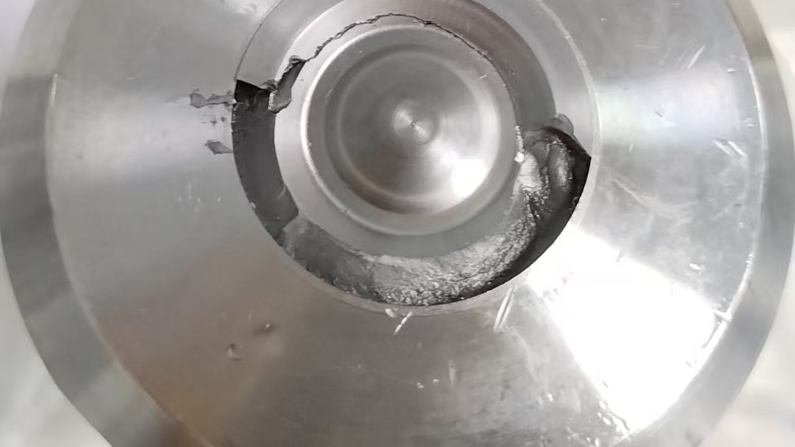
We start with the first damaged area, not the largest piece that later broke away. The position and direction of that first mark decide what should be measured next.
| What we see | Where it normally sends the inspection | The shortcut that causes trouble |
|---|---|---|
| A chip at one edge | Punch/die alignment, transfer center, support behind the loaded zone, a double blank or foreign material | Ordering the same geometry in a harder carbide |
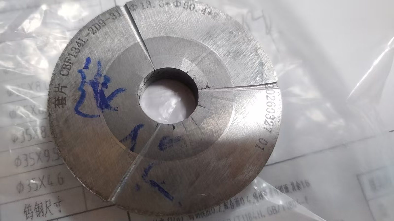
| A line running through the bore | Crack origin, insert OD, case bore, concentricity, assembly fit, case condition and clamping | Rejecting the insert as bad material before measuring the case |
| A rounded or polished working profile | Cycle count, dimensional drift, wire surface, lubricant coverage, cavity condition and grade choice | Calling it premature wear without a like-for-like production baseline |
| A corner that never filled | Cut-off length, blank volume, previous-station shape, transfer, punch timing and vent path | Opening the final cavity before checking the earlier stations |
This is the same logic we use when reviewing cold heading dies for bolts and screws: locate the load path first, then choose the material and construction.
Chipping: Read the First Impact Point
When the damage stays on one side, the location matters. Was the punch on center? Did the transfer present the blank squarely? Was there solid support behind that part of the insert? A double blank or broken wire end can leave a similar one-off overload mark.
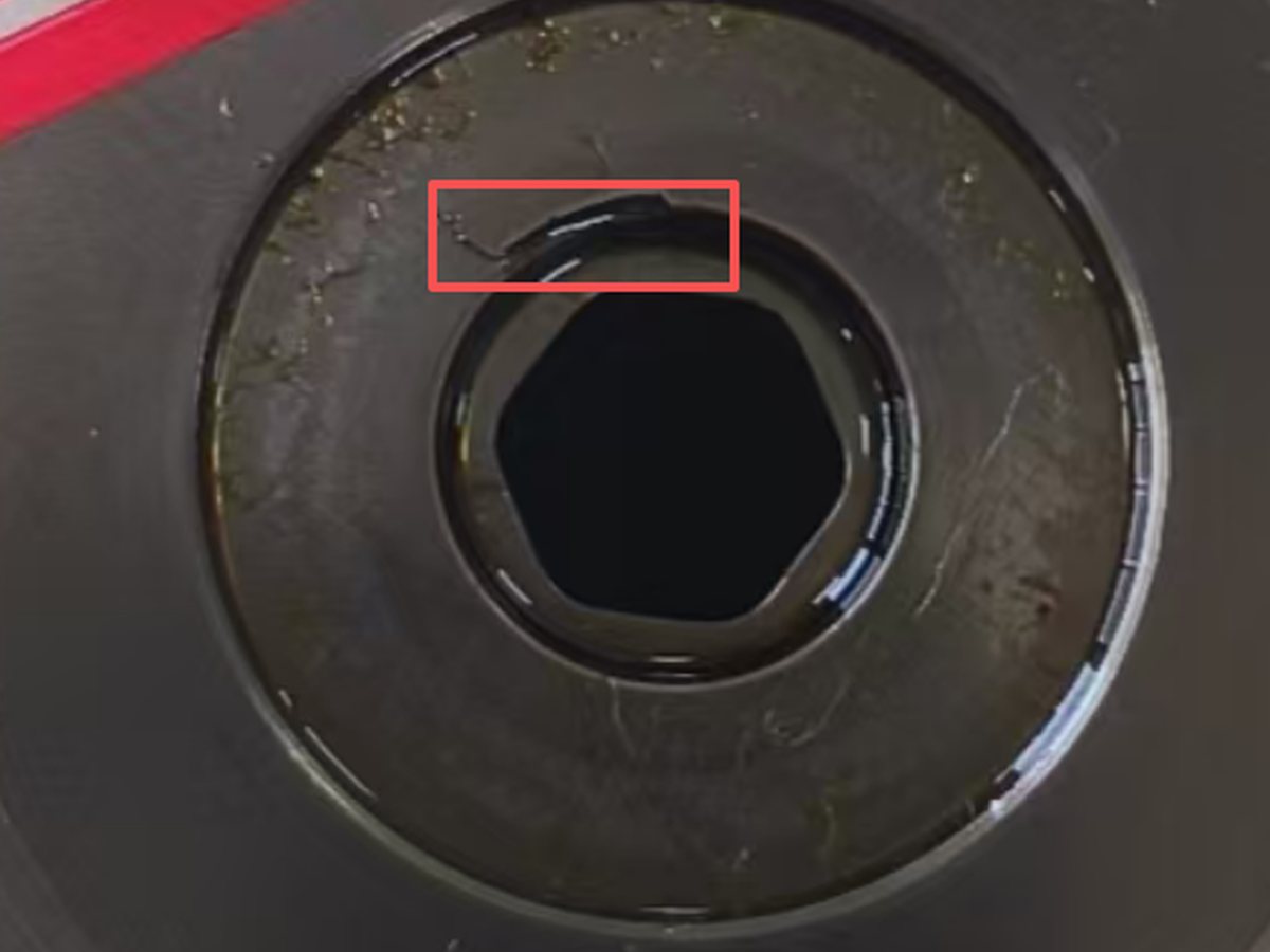
A grade change can hide the symptom for a while and still leave the load concentrated in the same place. A tougher carbide may absorb impact better but give up wear resistance. A harder grade may hold the profile and chip again at the unsupported edge. We therefore look at the support length, insert wall, transition radius and station load together.
The most useful note to send with the photograph is simple: did it break during setup, after a stable run, or immediately after a jam or other machine event? That one line is worth more than asking for a "stronger carbide die."
Cracking: Measure the Fit Before Blaming the Insert
The steel case is not just a holder. Its fit keeps the carbide under controlled compression while the bore sees forming load. Too little interference can allow movement. Too much, or an uneven fit, can load the bore before the first part is made.
Jungu internal starting values: heated shrink-fit assemblies are commonly reviewed around 0.7% interference, while cold press-fit assemblies may start around 1.0% interference. These are internal starting points, not universal pass/fail standards. Final interference depends on insert outside diameter, carbide grade and binder, wall thickness, case material and hardness, assembly method, and station load.
Interference ratio = diameter interference / carbide insert outside diameter x 100%.
Copying the old percentage into a new tool is risky. We need the measured insert OD and case bore before assembly, the measurement temperature, the assembly method and the direction in which the crack started. A bore-origin crack tells a different story from damage that starts at an unsupported outer corner.
If the case is out of round or damaged behind the insert, fitting a new carbide into it can repeat the same failure. Treat the die case and carbide die core as one loaded assembly, not two catalogue items.
Wear: Compare It Against the Same Job
"Short life" is not a measurement. We need the part count and the dimension that moved out of tolerance. Then we compare the same part, station, wire condition, speed and lubricant. Tool-life numbers from another fastener can be worse than useless because the load and sliding contact are different.
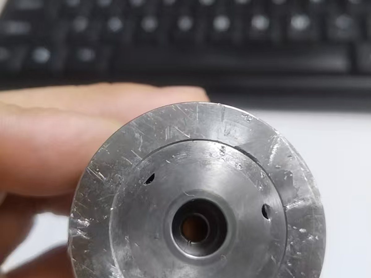
The material sheets we use make the trade-off clear: grades built around binder content and toughness do not also keep the highest hardness. Fine-grain, wear-focused grades can be less forgiving when impact is the real problem. Brand codes are not interchangeable, even when two rows look close on a comparison chart.
Before changing the grade, look for wire scale, rust, decarburized or damaged surface, broken lubricant coverage, pickup and a roughened cavity. The carbide versus tool steel guide covers the material route; the carbide wear testing guide explains why hardness alone does not predict service life.
Incomplete Fill: Look One Station Back
The final die is where the missing corner becomes obvious. It may not be where the mistake began. The available material volume, its shape and its position were already set by the cut-off and earlier stations.
| Final symptom | Earlier evidence to inspect | Likely correction route |
|---|---|---|
| Head corner does not fill | Cut-off length, blank weight, previous upset volume, and flash or material loss | Restore the required volume and distribution before changing the final corner |
| One side remains shallow | Transfer position, punch/die alignment, blank tilt, and asymmetric previous-station shape | Correct centering or transfer repeatability |
| Shoulder or extrusion is short | Previous punch stroke, penetration depth, timing, and station sequence | Review the earlier forming step and machine setting |
| Local void or trapped-air mark | Vent route, blocked relief, lubricant accumulation, and material flow path | Confirm venting and flow before enlarging the cavity |
Adding material is not a safe universal fix. A larger blank may fill the corner and overload the insert somewhere else. Blank correction has to follow the part drawing and the full forming sequence.
How We Work Through a Returned Die
- Find the first damage. We mark the chip edge, crack origin, wear track or unfilled feature. The final break is often only the last event.
- Put the timing back together. Setup condition, part count, last good sample, wire batch, lubricant and any recent machine change go on one line.
- Measure what held the insert. Insert OD, case bore, concentricity, support contact and case deformation are checked as an assembly.
- Lay out the adjacent stations. The previous blank, transfer position, punch, ejector and rejected part are compared side by side.
- Change the cause, not just the broken piece. The answer may be alignment, support, fit, grade, geometry, finish, lubrication, venting or an upstream process setting.
A photograph is useful. It is not a verdict. Its job is to tell us where to put the gauge and what to ask the operator.
For a multi-station replacement, see the carbide cold heading die route. When the part cannot release from a one-piece cavity, review the segmented dies engineering page before copying the failed assembly. The supplier checklist shows what a buyer should expect before accepting a final quotation.
What to Send With the Failed Tool
Do not clean away every clue before taking the photographs. Show the damage as found, then add the measurements and production record.
- Finished-part drawing and, when available, the tooling or assembly drawing.
- Machine brand/model, station number, forming sequence, production speed, and recent setup changes.
- Wire or blank material grade, hardness condition, diameter, cut-off length, surface condition, and lubrication route.
- Carbide insert OD, case bore, wall thickness, case material/hardness, support details, and assembly method.
- Failure photographs showing the cavity, crack path or chip, case, rejected part, and previous-station blank.
- Actual cycle count before failure, normal internal baseline for the same job, dimensional drift, and target production quantity.
- Whether the event happened during setup, after stable production, after a wire-batch change, or after a machine interruption.
Send the drawings, machine model, material and current failure photos. For confidential projects, remove the customer name and unrelated dimensions, but keep the geometry and measurements needed to diagnose the load path.
Cold Heading Die Failure FAQ
Can the same carbide die crack from both impact and fatigue?
It can. A hard hit may leave a crack too small to see, then normal forming cycles carry it across the insert. Check the fracture face against the machine-event record and part count.
Should I replace only the carbide insert or the entire die assembly?
Sometimes the insert is enough. First measure the case. If it is out of round, deformed or damaged behind the insert, a new carbide can fail in the same way.
What is the most common carbide-grade selection mistake?
Going straight to the hardest grade. Hardness may help wear, but it does not repair poor alignment, weak support or a thin insert wall under impact.
Does incomplete fill always mean the final die cavity is wrong?
No. The final cavity may only be where an earlier error becomes visible. Check blank volume, the previous-station shape, transfer centering, punch timing and venting first.
How can I tell whether wear is normal without a public tool-life benchmark?
Use your own last stable run as the baseline. Compare the same part, material, station, speed, lubricant and acceptance limit, then record both part count and dimensional drift.
Can Coolant, Storage or Heat Contribute to Die Failure?
A stain on a steel case is not proof that the carbide insert failed by corrosion. Identify the affected surface before changing material: exposed steel, the carbide surface, the insert boundary and dried coolant deposits need different checks. The failed-tool photographs above show mechanical damage; they are not corrosion examples.
If damage follows a coolant change or a long shutdown, record the coolant product, concentration, supplier control limits, cleaning method and storage conditions. Keep the first photographs before cleaning. Review coolant compatibility with the carbide and lubricant suppliers rather than assuming that all cemented-carbide grades respond alike.
For suspected heat-related damage, distinguish the measured tool temperature from the workpiece temperature and note where and when it was measured. A generic tungsten-carbide temperature limit is not a safe operating limit for an assembled die: the binder, case, coating, fit and exposure conditions also matter.
- Check lubrication delivery and contact marks before increasing production speed.
- Use the approved cleaning and storage procedure; dry recesses and protect exposed steel as specified.
- Send the grade designation and process history with the failed tool. The carbide grade and hardness guide explains what supplier data can and cannot establish.