
Cold Heading Defects: Folds Under a Bolt Head
A line on the underside of a cold-headed bolt can be a fold, a seam carried in from the wire, or a mark left by tooling. Photograph it before the part goes to heat treatment or coating, if the sample comes from the heading line. Mark where the line sits on the drawing and keep the part with its lot and station identification. Those details give the toolmaker and the quality team a common starting point.
Locate the line before naming the defect
Look at the bearing face, where the underside of the head seats against the joint. Does the indication follow the outer edge of the flange, sit on the head-to-shank radius, or continue along the shank? Take an overall photo to show the location and a close-up with a scale. On a round flange, state what you used as an angular reference, such as a head flat. Keep a previously accepted part of the same drawing revision for comparison if one is available.
A forming fold can develop when material rolls over onto itself. A raw-material seam can be carried into the head as the wire is formed. Surface appearance alone leaves both possibilities open. Dubiel and Balawender investigated three cases of discontinuities on bolt head bearing surfaces using experiments and simulation. Their work gives a reason to examine the part at intermediate stages as well as after the final blow. Bolt head bearing surface study.
Compare the samples before ordering a new die
Use the table to choose the next sample or record to request. Start with retained parts when possible. Collect additional samples only under the plant’s approved procedure.
| Observation | What to compare | Who should review it |
|---|---|---|
| Line along the shank that reaches the head | Retained wire from the same coil, early-stage samples and the wire lot record. | Materials quality and the wire supplier. |
| Line appears after the flange takes its final shape | Samples from the preceding and final stations. If sectioning is needed, mark where the cut should cross the line. | Quality and the toolmaker, with both station drawings. |
| Similar marks recur at the same position on consecutive parts | The relevant contact face on the die or punch and an accepted sample with the same orientation. | Tooling or maintenance, with the tool revision and station identified. |
| Line first reported after heat treatment or coating | Retained samples before and after the operation, matched by lot and processing route. | Quality and the processing supplier. |
For example, a flange bolt shows an arc near its outer rim. The line is apparent on the final headed sample and absent on the preceding sample under the same inspection conditions. Retain both pieces and ask quality to agree a section location if the source remains unclear. Bring the preceding preform drawing and the finish-tool drawing to the review. This is a hypothetical example. The stage where the line becomes visible narrows the review, and a section can help show whether the surface folds back into the part or the indication is a shallow groove.
Specify the acceptance requirement in the order
The drawing and purchase order should identify the governing document and edition, the surfaces to inspect, the agreed method and the sampling or reporting plan. Set out any drawing-specific requirement for the bearing face or underhead radius before the tooling quote. The figures below describe the published scope of two references for metric parts.
| Reference | Metric scope excerpt |
|---|---|
| ISO 6157-1:1988 | Nominal thread diameter ≥ 5 mm, product grades A and B, property classes up to 10.9 for its general scope. |
| ASTM F788/F788M-20(2025) | Metric nominal diameter ≥ 4 mm and specified minimum tensile strength ≥ 420 MPa, within its stated product scope. |
The diameters and strength in the table describe which products the references cover. For a disposition, use the applicable clause for the discontinuity and its location, together with the drawing and order. If the tooling trial uses unthreaded blanks, state which checks apply to the blank and which will be repeated on the finished fastener.
Keep the inspection result tied to the actual part
When you request a section, give the lab the marked part and the overview photo so the reported plane can be found again. Ask the report to distinguish what was visible on the surface from what the section actually showed. A line that cannot be located again is poor evidence for changing a tool. If the lot is on hold, keep the sectioned sample, its untouched companion and their IDs together.
When a new die is part of the response, agree on two separate checks for the trial. First, confirm the usual head dimensions on the drawing. Then record the appearance of the bearing face and underhead radius against the agreed inspection requirement. For a proposed change to the preform, keep a labelled sample from the revised station. The guide to laying out the forming sequence explains what to put on that drawing.
What should go in the tooling request?
Send the part and preform drawings, station number, material condition, affected lot, and labelled photos or section report. Mark the inspection zone on the part drawing. If the enquiry is for a replacement insert, identify the existing case and its mounting dimensions. If the supplier is also reviewing the forming sequence, ask which intermediate samples the proposed trial will retain and how they will be identified.
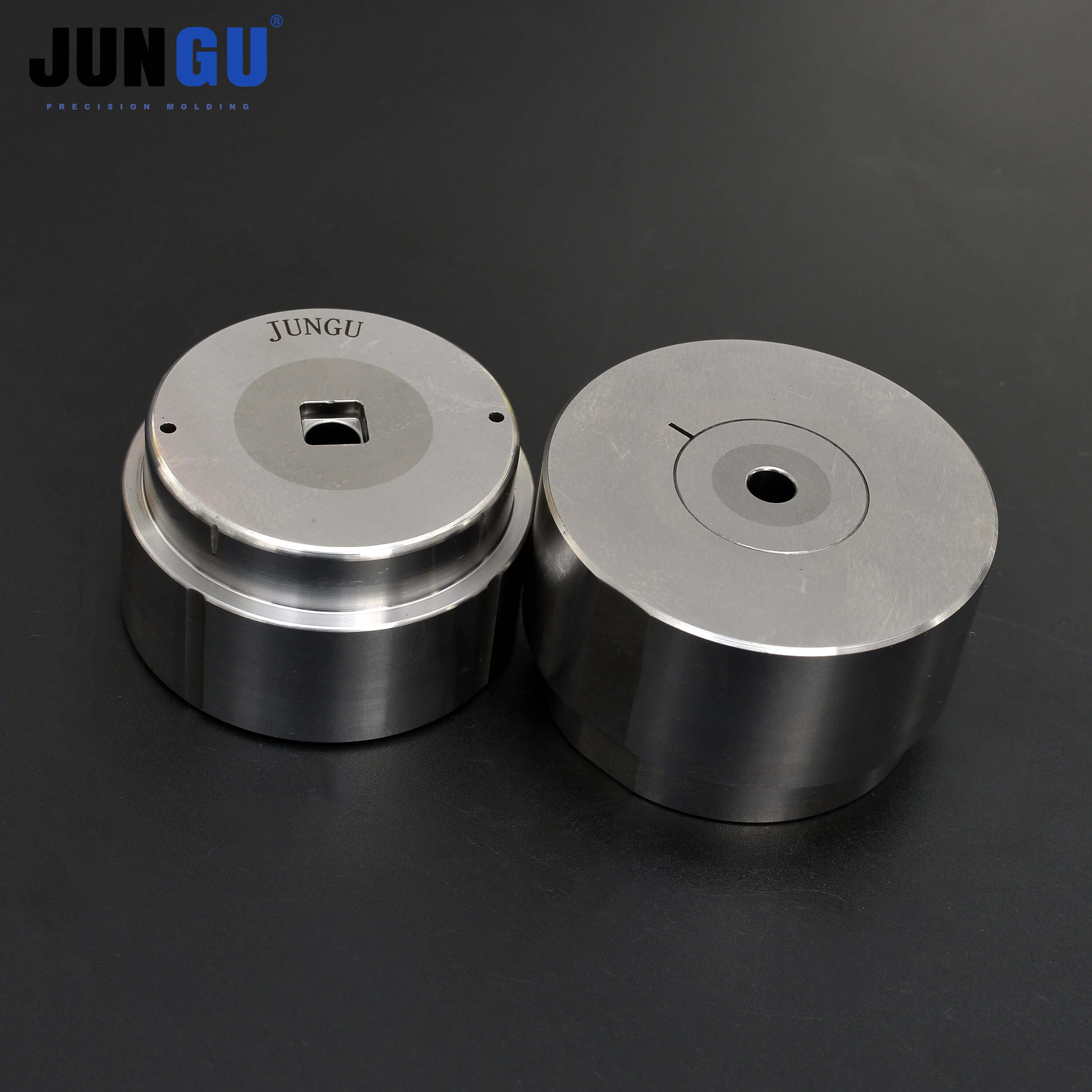
See the custom bolt cold-heading die or the bolt and screw forming die range. Send your drawings and the inspection record for a tooling quote.