
Cold Heading Maintenance: Check the Transfer After a Tool Change
After a tooling change on a multi-station cold former, check how the part leaves one die and enters the next before ordering a replacement transfer finger. A finger can fit its holder and still grip the wrong surface of the partially formed part. Label the handoff by station, compare it with an accepted setup, and send the mounting and gripping details with the drawing.
Put the station handoff on the setup record
For cold heading maintenance after a changeover, keep the transfer finger, its holder, and the incoming and receiving tooling on the same setup record. Identify the station the part leaves, the station it enters, the gripping surface and the intended orientation. Record the finger drawing revision, its side as viewed from a stated direction, and the holder or cassette reference. A photograph of the finger on a bench cannot show the orientation of the handoff.
Identify which component holds the part at the instant before pickup. If the source tool has not presented the part in the approved position, check the part’s ejected position against the setup record first. If it is presented consistently but reaches the next die tilted or turned, collect evidence on grip, release and the receiving approach. Use the machine maker’s procedure and site safety rules for setup, observation and sample collection. Keep your hands out of the tooling area during machine motion.
The transfer design affects what can be recorded and restored. SACMA describes timed finger motion and gives an example of a setup system that stores settings by product code. Check which settings your machine stores and which depend on tooling and holders installed during the changeover. Use your machine’s instructions to identify the approved setup record and corresponding tooling references. SACMA transfer system.
Use the first point where a sample changes
The table is a guide to collecting evidence. A mark or a part out of position may have several causes. Compare observations from the same part revision under the same documented conditions and use accepted samples where available.
| Observation | Evidence to collect | First review |
|---|---|---|
| Part position changes before pickup | Ejected part position and previous-stage sample | Check the source tool and ejection record. |
| A mark appears at the grip | Mark location on the part, contact profile and accepted sample | Compare the gripping surfaces and the intermediate part geometry. |
| Part is square at pickup and tilted at entry | Orientation at both points and holder identification | Ask maintenance to review the transfer path, release and receiving interface. |
Trace a new mark through one handoff
Suppose a new mark is seen on the neck of a headed blank after a changeover. In an approved trial, the blank leaving station two is unmarked. The sample entering station three shows the mark on the same surface touched by the grip. That comparison narrows the review to the handoff. It leaves open whether the contact comes from the finger profile, the holder’s position or an obstruction on the way into station three.
Record the mark on a photo with the station numbers and the clock position relative to a visible part feature. Pair it with a photo or sketch of the corresponding transfer interface. If the blank already carries the mark before pickup, send the earlier sample back to the review of station two. If the transfer presents the part correctly but the mark appears only after the next forming operation, include the receiving die and punch in the investigation.
Before release, compare the agreed intermediate characteristics and the relevant finished dimensions against the approved drawing and control plan. Have maintenance review the machine or holder interface when the difference persists with a known good finger. National Machinery also recommends bringing part observations and maintenance history to the assessment and validating the affected operation with samples after a repair. National Machinery’s cold former rebuild guide.
Specify a replacement finger from the machine side and the part side
Send the mounting drawing, reference faces, fastener or locating features, and the gripping profile for the intermediate part. Include the machine model, holder version, hand or side, and whether the quotation is for one finger or for the two members of a matched set. Where the original drawing is unavailable, identify the sample as used and mark the surfaces likely to have worn. Request agreement on the reference geometry before treating the sample as a manufacturing master.
Include the clearance interfaces with the neighboring die and punch if the drawing shows them. Ask which dimensions the supplier can inspect on the loose component and what the plant must confirm in the installed condition. Inspection of new fingers can verify the part drawing. Trial parts and an approved machine check provide the evidence for releasing the handoff to production.
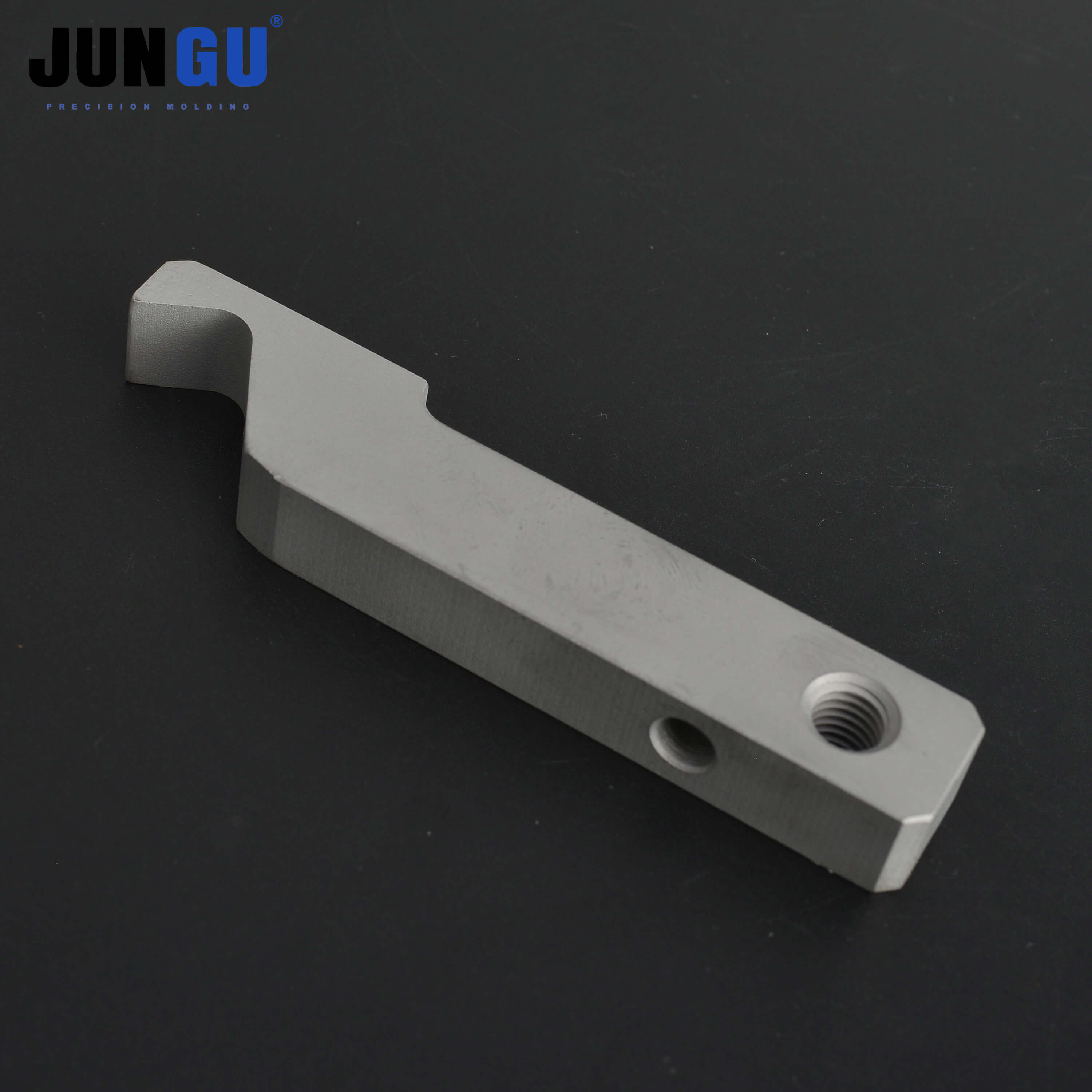
See the multi-station transfer finger, cold former tooling and parts and forming sequence guide. Send the finger or holder drawing and the intermediate part at the handoff for a drawing review.