
Cold Heading Head-to-Wire Ratio and Upset Length
The head diameter divided by the wire diameter describes how wide the head becomes. It does not tell you how much unsupported stock a single blow must upset. For a bolt or screw tooling enquiry, ask the supplier to show the head material requirement and the unsupported length at each heading blow separately.
Keep three quantities separate
Head-to-wire ratio: divide the intended head diameter by the incoming wire diameter. State the drawing stage and the diameter being compared. For a non-round head, identify which dimension you are quoting, such as across flats.
Equivalent wire length for the head: divide the head volume by the incoming wire's cross-sectional area. Use the as-headed geometry with a defined head-to-shank boundary. A recess, fillet or subsequent trimming operation can change which volume belongs in the calculation.
Unsupported length at a blow: check the stock that is unsupported as the punch begins to load it, using the preform and tool arrangement for that blow. The equivalent wire length is a material estimate. Support from the die or punch and the intermediate shape determine how much stock is actually unsupported.
Same head diameter, different stock demand
For illustration, take 6 mm round wire and two ideal solid cylindrical heads, each 12 mm across. Ignore fillets, recesses and material removal. Both heads give the same head-to-wire ratio of 2. Their thicknesses give different head volumes.
| Head thickness | Head volume | Equivalent length of 6 mm wire |
|---|---|---|
| 2 mm | 72π mm³ | 8 mm |
| 4 mm | 144π mm³ | 16 mm |
The thicker head takes twice the head stock even though the diameter ratio stays the same. Neither result specifies an unsupported length or approves a blow count. Carpenter Technology's heading guide uses head volume and wire size to relate an upset to its stock requirement. National Machinery's forming principles explain the role of upsetting in making enlarged sections.
What to ask for in the tooling proposal
Provide the as-headed drawing, wire diameter and supplied condition. Ask for the incoming preform sketch for each proposed heading blow, with the supported and unsupported portions marked. If the supplier proposes a preform blow, ask what shape it leaves and how the next blow supports that shape. Agree which intermediate sample and head features will be inspected in the trial. This gives both teams a way to review a fold or an underfilled head without assuming the final cavity is the cause.
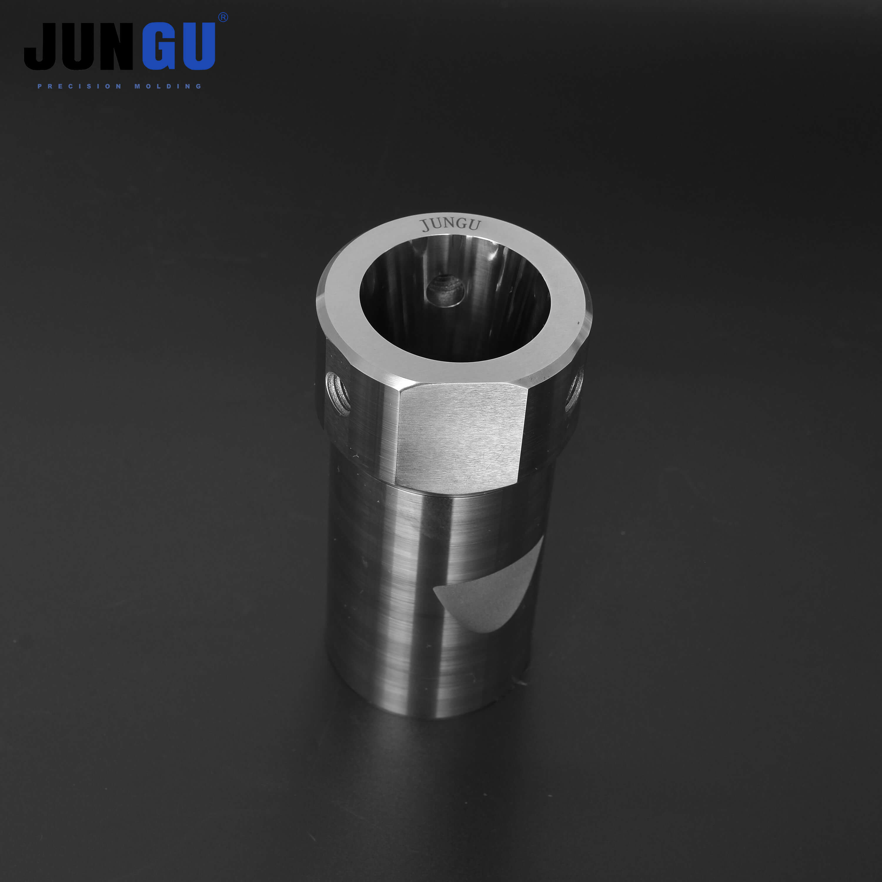
See the first-upset punch case, bolt and screw forming dies and the forming sequence guide for the broader station review.
Can I approve a one-blow design from the head-to-wire ratio?
Use the ratio to describe the geometry. Approval also needs the material condition, machine limits, tool support and evidence from the proposed forming route.
Send Jungu the head drawing, wire condition and proposed preform for a tooling enquiry.