
Cold Heading Tolerances: What to Check on the First Piece
A headed bolt can pass at the press and fail on the final inspection bench. Before changing the cold heading die, find out whether both inspectors measured the same feature in the same condition. A head-height reading taken before trimming and a reading from the finished bearing face may answer different questions, even when both reports call the feature “head height.”
Put the inspection stage next to each critical dimension
Start with the finished drawing and mark the features this tool actually forms. For each one, tell the die maker whether it must meet the drawing straight off the header, after a later sizing operation or only in the finished condition. If an operation will remove a surface or establish a new face, give the supplier the intermediate drawing or a marked section. A finished drawing can be enough to discuss the job, but it may omit the shape the tool needs to leave for the next station.
For a head height, draw the two surfaces used for the measurement. If the measuring foot can touch a raised mark, a radius or a flash remnant, agree where it should sit. For a shank that has a step or taper, identify the axial section and measurement directions. If you need the head located relative to the shank, use the geometric control and references on the drawing. A diameter reading alone gives little evidence about head location. When the drawing invokes ASME Y14.5, confirm the edition and apply its rules for the specified control.
The ASM Handbook chapter on cold heading discusses process sequence and shows dimensional variation for specific cold-headed parts. Carpenter Technology's heading guide describes how attainable tolerances vary with the style of upset and forming method. Treat published examples as context for the drawing review. A meaningful quotation states the actual feature, material condition, process stage and method that will be used to judge it.
Follow one lot through the handover
Imagine a bolt head that meets the intermediate height range at the press but comes out low after a downstream operation. The values below are invented for this example. The finished and intermediate ranges happen to be the same to make the comparison clear. Real stage limits come from the approved drawings and may differ.
| Check | Example limits | Example result |
|---|---|---|
| Head height at press exit | 4.95–5.05 | 5.02, within intermediate limits |
| Head height after downstream operation | 4.95–5.05 | 4.92, 0.03 below final lower limit |
| Difference between readings | Diagnostic value only | −0.10, if both readings use comparable surfaces |
First check the sample ID and how each report establishes the bearing face. If the references and methods are comparable, take the two results to the owner of the operation between them. If the references differ, repeat the checks with the agreed method before interpreting the 0.10 mm difference. This example identifies a place to investigate. It cannot establish what removed or moved material, or how much a die should be corrected.
If the press-exit sample already falls below its own limit, keep it alongside a known good blank. Record the stock condition and die and punch revisions. Ask the toolmaker whether they need the cutoff length or mass, a photo of the fill around the head or a sample from an earlier blow. A uniformly low head and a head with one corner missing point to different evidence. Give the supplier the measured values and where the shortfall appears before asking for a different cavity.
Separate first-piece approval from repeatability
A conforming first piece is evidence about the sampled setup. If the purchase specification also requires capability, agree which feature, sampling plan and measurement system will be used. Keep the order of the readings and identify changes in wire lot, setup or tooling. Mixing readings from different stages can hide a shift and leaves the supplier unable to identify which operation controls the result. The NIST process capability guide compares the behavior of a stable process with specification limits. A single first-piece reading cannot demonstrate that stability.
Put the deliverables in the request. A tool inspection report should identify the tool dimensions and revision. A first-piece report should identify the bolt sample and stage, actual readings and inspection reference. A capability request should describe the production conditions it is meant to cover. If the tool supplier will only see parts from a trial press, agree who will verify the intended production line and final operation. This avoids accepting one stage and expecting the report to cover another.
When the buyer and supplier disagree on the reading, send the inspection setup as well as the number. A drawing with the contact points marked, a sample ID and a photo showing how the part rests in the fixture are often enough to find a mismatch. If the same sample passes on one instrument and fails on another, have quality run both methods on that sample before changing a setting. If both methods agree and the values drift over the run, keep the time sequence and identify the first change in tooling, stock or setup. That gives engineering a usable comparison instead of a single rejected number.
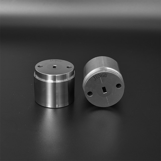
See the bolt forming die, bolt and screw tooling range, and the forming sequence guide. Send Jungu the finished drawing, the marked intermediate feature and the two inspection records so the tooling review starts at the right station.