
Bolt & Screw Forming Dies
Metal Die Bolt Tooling for Engineering Parts
Metal die bolt tooling for engineering cold-formed parts. Jungu checks drawing tolerance, blank control, station load, cavity support, material route, and defect evidence before quoting.
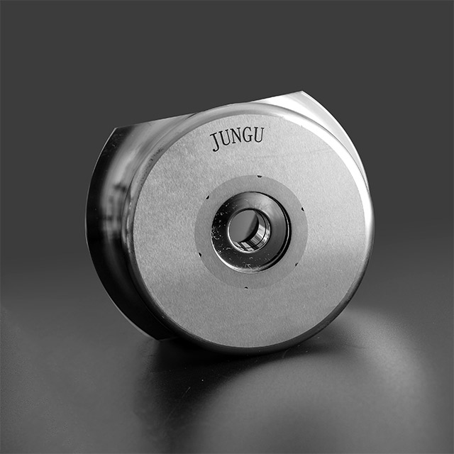
When does a cold-formed engineering part need dedicated die tooling?
Metal die bolt tooling for engineering parts is used when a cold-formed component cannot be reviewed as a conventional bolt-head cavity. The deciding features may be a non-standard head, shoulder, shank transition, functional contact surface, or an inspection requirement tied to assembly. Two parts with a similar outside shape can still require different cavity support or forming sequences, so a product photo is not enough for quotation. Jungu reviews the drawing with functional surfaces marked, available blank and material data, station sequence, die-case interface, release direction, current defect location, and the buyer's inspection result. Fold marks, incomplete fill, sticking, eccentricity, cracks, or dimensional drift are compared with the process information before the tooling route is selected. This keeps the page focused on non-standard engineering geometry; standard bolt and screw cold-heading tooling remains on the separate bolt-tooling page.
Common sourcing use
Non-standard cold-formed engineering parts where functional surfaces, shoulders, transitions, die support, and the inspection method must be reviewed together.
Related product families
When does the part need an engineering-tooling review?
Use this page when the component has non-standard shoulders, shank transitions, functional contact surfaces, or drawing tolerances that cannot be treated as a conventional bolt-head cavity. If the job is a standard bolt or screw cold-heading sequence and the main questions are blank volume, head fill, die-case support, and release, use the bolt tooling page.
Technical Review Scope
What Jungu checks
- Engineering drawing with functional surfaces, shoulder transitions, critical tolerances, datum references, and inspection method marked
- Available blank diameter and cut-length data, material grade, hardness information, lubrication, and surface condition
- Machine station, forming sequence, die-case interface, release direction, cavity finish, and available load or setup information
- Failure evidence: fold mark, crack, sticking, incomplete fill, eccentricity, dimensional drift, or failed gauge result
Why no standard price is shown
Engineering-part tooling is quoted after the functional surfaces and inspection priorities are identified. Custom shoulders, transitions, cavity support, forming sequence, material, and defect evidence can change the die route even when the outside size looks similar to a bolt die.
Information Needed for Quotation
| Drawing priority | Marked functional surfaces, critical dimensions, shoulder transitions, datum references, and inspection method. |
|---|---|
| Blank and material | Available blank diameter and cut-length data, material grade, hardness information, lubrication, and surface condition. |
| Tooling context | Station sequence, die-case interface, release direction, current tool photos, and available process information. |
| Defect evidence | Photos of folds, cracks, sticking, incomplete fill, drifted dimensions, failed gauges, or the affected die area. |
Application and Buyer Fit
| Typical application | non-standard cold-formed engineering parts where functional surfaces, shoulders, transitions, die support, and the inspection method must be reviewed together |
|---|---|
| Buyer review focus | functional geometry, blank data, material, station load, cavity radius, release angle, die support, and measurement drift |
| Quotation basis | marked drawing, available blank and material data, station sequence, die-case interface, inspection method, and defect evidence |
| Review output | a metal die route matched to the engineering drawing, forming sequence, support structure, and inspection target |
Inquiry Process
- Send the drawing with functional surfaces marked, available blank and material data, station sequence, current tool photos, and rejected-part evidence.
- Jungu separates cavity-geometry risk from blank control, process sequence, die-case support, release direction, and inspection setup.
- Engineering reviews the cavity route, support structure, material and surface-treatment requirements, forming sequence, and inspection points.
- A quotation is prepared after the tooling route and technical review scope are clear.
FAQ
Can a standard bolt die route be used?
Only when the functional surfaces, transitions, forming sequence, and inspection requirement match a conventional bolt. A similar outside shape is not enough.
Why can the same die produce dimensional drift?
The cause may be the blank, material condition, lubrication, station setup, die support, cavity condition, or inspection method. Compare process data with the defect location before changing the cavity.
What drawing marks are useful?
Mark the functional surfaces, datum references, tolerance-critical dimensions, inspection method, and the location where the current part fails.
Why should functional surfaces be marked on the drawing?
They show which dimensions and transitions control assembly or performance. That lets engineering focus cavity support, finishing, and inspection on the areas that matter to acceptance.
Need this tooling reviewed?
Send drawings, machine model, material, and current failure photos for review.