
Carbide Punch Profile Grinding: What the Drawing Must Define
For custom carbide punch profile grinding, define the required geometry before choosing the process name. The quotation needs more than a tip outline: it needs the profile's relationship to the mounting surfaces, the length over which that shape applies, the corner requirements and an agreed way to inspect them. A supplier's machine specification is not an acceptance tolerance for your punch.
This guide addresses drawing review for a new or replacement profiled punch. It is not a grinding recipe or a promise that every recess can be produced by profile grinding. Internal cavities, external contours and assembled tools can require different manufacturing and inspection routes.
What does profile grinding actually specify?
Profile grinding describes a manufacturing operation. For example, AMADA lists the GLS 150GL as an optical profile grinder with an LED projector. That confirms a type of equipment, not a universal capability for every carbide geometry. It does not establish which equipment Jungu would use for a particular order.
Start with the tool's function and accessible geometry. Is the drawing for an external punch tip, a shaped insert or an internal recess? Mark the faces requiring the finished profile and identify surrounding material that could restrict access. Ask the supplier to confirm the route against the drawing, including any preliminary machining and final inspection. Use Jungu's header punches and punch pins page to identify the relevant tooling family.
Define the contour in relation to the mounting reference
A nominal outline describes shape. It does not, by itself, define where that shape must lie relative to the installed tool. Identify the locating diameter, seating face or orientation feature that the assembly actually uses. Then state the necessary location and orientation requirements on the controlled drawing.
Consider a hypothetical punch whose tip outline is correct but shifted relative to its locating shank. An outline-only comparison could miss the relationship that matters during assembly. This is a drawing-review example, not a reported production defect. The inspection plan should preserve the specified reference relationship rather than freely repositioning the measured outline until it appears to match.
Separate the requirements on the drawing
| Requirement | Clarify before quotation | Evidence to agree |
|---|---|---|
| Nominal contour | Which drawing or model revision defines the working shape? Which views or sections control it? | Profile results linked to the same controlled revision. |
| Mounting relationship | Which surfaces locate and orient the tool? How is the working contour related to them? | Inspection setup and reported location/orientation characteristics. |
| Working length | Where does the working section begin and end? Are taper or relief features specified? | Checks at the drawing-defined sections and axial references. |
| Corner transitions | Which radii or edge conditions are functional? Are unspecified corners still unresolved? | Feature-specific results using a method suitable for access and size. |
| Surface and delivery state | What surface requirement applies, where is it evaluated, and is acceptance before or after any specified coating? | Separate dimensional, surface and final-state records as required. |
Do not fill an unspecified radius with a convenient catalogue minimum. Likewise, a general note such as “polish” should not silently change the nominal profile or define a numerical surface requirement. Resolve these points before manufacture. For surface finishing rather than creation of a new contour, see the separate carbide die polishing guide.
Ask what the profile report proves
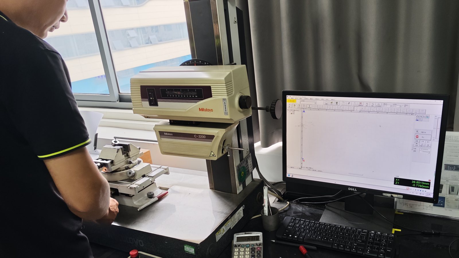
Mitutoyo describes its M2 profile-projector package as supporting two-dimensional geometric measurement and reporting. When using this kind of evidence, identify the measured view and the characteristics being evaluated. A satisfactory outline in one view should not be presented as proof of every section, mounting relationship or surface requirement.
Before sample approval, ask the supplier to identify the part, drawing revision, measured features, reference setup and applicable limits in the report. Where several views or methods are needed, connect them to one part identifier. A photograph of a screen without those links is useful context but an incomplete acceptance record.
Compare quotations on the same scope
Two suppliers may both offer “carbide profile grinding” while quoting different deliverables. One may include only contour finishing; another may include the shank, supporting body, coating and inspection. State whether you are buying a finished punch, an insert or work on a supplied blank. Record who supplies the carbide specification and who approves the final drawing.
For Jungu's drawing-based enquiry route, review the custom carbide die bolt punch tooling page. Its internal-profile and support questions also help identify cases that need a different route from an exposed external profile. Do not order a component solely because its product name resembles the process requested.
Questions before drawing release
Does a smaller tolerance automatically require optical profile grinding?
No process should be selected from the tolerance number alone. Geometry, material, access and the required inspection relationship all need review. Ask for a proposed route and evidence matched to the actual feature.
Can a CAD outline replace the tool drawing?
An outline may define nominal geometry, but it should not leave mounting references, working length, material and acceptance requirements unstated. Identify which file controls each requirement and resolve conflicts between files before release.
What should a buyer send?
Send the tool and assembly drawings, available model, revisions, carbide requirement, working section, critical features and inspection expectations. For replacements, label wear photographs separately from nominal geometry. Send the drawings to Jungu for a tooling-route review before confirming the manufacturing scope.