
Apple Charger Plug Pin Mold: Case Study on Production Challenges and Solutions
Case study on charger plug pin mold design: copper alloy forming risk, scratch control, profile compensation, inspection points, and RFQ inputs.
Source basis: Jungu customer project records and technical review notes. Customer names, drawings, and production data are anonymized unless publication was authorized.
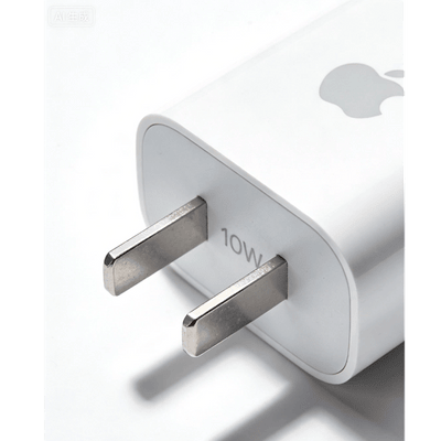
Short answer: for charger plug pin molds, the first failure point to check is not the cavity outline. It is surface finish, edge-radius control, and whether the drawing defines plating-sensitive dimensions clearly enough. For contact areas that will be plated, a buyer may need to specify requirements such as Ra ≤ 0.2 μm, critical edge radius control around ±0.02 mm, Ni plating thickness such as 1.5–3 μm, and base material condition such as H62 brass at HV 120–160. If these details are missing, a quoted price is only a placeholder.
This case discusses tooling requirements for Apple charger plug pin-type AC blades. It should be read as a manufacturing capability case, not as an end-customer endorsement. The useful lesson for buyers is how to review plug pin geometry, copper alloy flow, surface defects, and mold-life risk before starting a custom mold order.
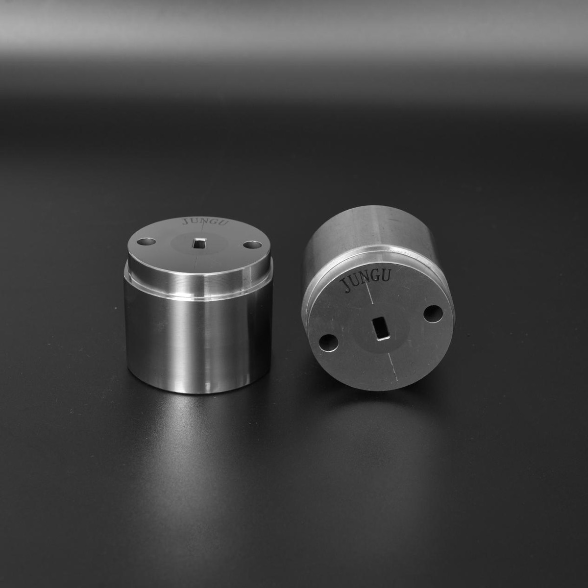
Why Are Charger Plug Pin Molds Difficult to Keep Stable?
Charger plug pins look simple from the outside, but the production window is narrow. A small drift in thickness or width can change insertion feel, plating coverage, and electrical contact stability. A small scratch on the forming surface can become a visible defect after plating.
For copper alloy or brass plug pins, we normally review four risk points before quoting:
| Risk point | When it becomes a critical risk | What Jungu checks |
|---|---|---|
| Material flow | Step-position drift around ±0.03 mm or visible local thinning near the formed step. | Forming sequence, relief angles, transition radii, and springback compensation. |
| Surface friction | Scratch marks that may still be visible after nickel plating or other surface treatment. | Mirror polishing route, coating options such as TiN/DLC where suitable, and lubrication contact points. |
| Guiding rigidity | Early clearance growth around 0.01 mm can start one-sided wear on narrow plug-pin geometry. | Guide pin clearance, punch support span, alignment stability, and maintenance access. |
| Heat treatment balance | Too soft means fast wear; too brittle at sharp edges increases chipping risk. | Tool steel route, possible carbide insert use, case depth, hardness-toughness balance, and edge design. |
What Failure Patterns Should Buyers Check Before Reordering?
When a buyer says "the plug pin mold wears too fast," we do not start from steel grade. We first ask where the defect appears. The location usually tells us whether the problem comes from material flow, friction, guiding, or heat treatment.
- Scratches on the broad face: often linked to surface finish, lubrication, coating, or local galling.
- Step-position drift: usually points to guiding rigidity, clearance growth, or springback compensation.
- Edge burrs or micro-cracks: can come from sharp transitions, excessive local pressure, or a brittle edge condition.
- Frequent shutdown for polishing: indicates the friction zone was not solved at the mold-design stage.
One distinction we check early is the base alloy. H62 brass normally behaves differently from pure copper such as C1100. Copper is stickier in contact zones, so the tooling review may require broader lubrication coverage and a larger fillet radius such as R0.3 mm where the drawing allows. Sending the exact alloy grade changes the mold steel selection, coating route, and polishing requirement.
For a replacement project, photos of rejected parts are more useful than a general statement such as "short tool life." Send close-ups of scratches, wear marks, and the current mold contact area.
How Does Jungu Review the Mold Route?
Jungu reviews a charger plug pin mold by separating shape control, surface control, and production stability. The review normally covers the part drawing, material grade, strip or wire condition, forming sequence, plating requirement, target volume, and current failure mode.
The engineering route may include a tough tool-steel base, selected carbide inserts, nitriding, TiN/TiCN-type coatings, mirror polishing in contact zones, or controlled transition radii near stress-sensitive edges. The right route depends on the drawing and the existing defect, not on a universal "best material" claim.
For high-volume plug pin work, we also check whether maintenance can be done without disturbing the whole setup. If a wear zone is predictable, the mold structure should make that area inspectable and replaceable.
What Quality Checks Should Be Confirmed Before Shipment?
For plug pin molds, a buyer should not accept a shipment only because the mold looks clean. The inspection should connect directly to the drawing and the visible defects the buyer wants to avoid.
| Check item | Why it matters |
|---|---|
| Critical cavity and punch dimensions | Controls thickness, width, step position, and repeatability. |
| Contact-surface polish | Reduces scratch initiation and supports smoother copper alloy flow. |
| Surface roughness on forming flanks | Helps prevent micro-scratches that become more visible after plating. |
| Transition radii and edge condition | Reduces local stress and micro-crack risk near sharp geometry. |
| Hardness and heat-treatment consistency | Supports predictable wear without sacrificing edge toughness. |
| Drawing-to-sample review | Prevents a mold from being accepted before the buyer checks the real forming target. |
What Should You Send for a Reliable RFQ?
For this type of project, a five-minute price is rarely a real technical quotation. Before asking for final price, send:
- 2D or 3D drawing with thickness, width, step dimensions, and tolerance notes.
- Material grade, hardness or temper condition, and whether the part is copper alloy, brass, or another conductive material.
- Plating requirement and visible-surface requirement.
- Target production volume and current maintenance interval if this is a replacement mold.
- Photos of rejected parts, especially scratches, galling marks, burrs, and step drift.
- Machine type, forming process, and any known lubrication or coating requirement.
Bottom line: send the drawing, material grade, plating requirement, and failed-part photos before asking for a final price. We can review the tooling route first, then quote with fewer hidden assumptions.
FAQ
Can Jungu quote a charger plug pin mold without a drawing? Only roughly. A reliable quote needs the drawing, material grade, critical tolerances, plating requirement, and the target production volume.
What causes scratches on charger plug pins? Common causes include rough contact surfaces, galling, insufficient lubrication, poor coating selection, and local pressure concentration in the forming zone.
Should the mold use carbide or tool steel? It depends on the material, geometry, contact pressure, production volume, and maintenance target. Jungu reviews the drawing and failure mode before recommending tool steel, carbide inserts, surface treatment, or a combined structure.
What photos help the fastest review? Send close-up photos of rejected pins, scratches, burrs, worn mold areas, and the current tool setup. Mark the defect location if possible.
Why do plug pins pass visual inspection but fail scratch checks after plating? Micro-scratches that are difficult to see on bare copper alloy can become more visible after nickel plating, especially when the plating layer follows the forming marks. For plating-sensitive parts, Jungu checks the forming flanks, not only the flat face, and polishes critical contact areas toward the required surface-finish target before shipment. Tell your supplier the plating specification upfront, or the mold may be polished to 'looks good' instead of 'plates well'.
Can this case be used for other small electrical contact parts? Yes. The same review logic applies to many small conductive parts where surface finish, dimensional stability, and plating quality are tied to the mold design.