
How to Calculate Thread Rolling Load for a Tooling Inquiry
To calculate thread rolling load for a tooling inquiry, first identify which force you need. The ideal force from a hydraulic piston can be calculated from pressure and area. The load needed to form the thread depends on the workpiece, dies and engagement during the pass. A machine rating sets another limit. Keep these values in separate fields on the inquiry.
Read the pressure and force units before comparing machines
A gauge reading in bar or psi is pressure. A catalogue value in kN or pounds-force is force, even when the catalogue calls the field “rolling pressure.” Check where the force applies, its direction and whether the value is a maximum or an available force under defined operating conditions. A spindle power rating in kW or horsepower answers a different question.
Tesker publishes the following figures for two of its two-die machines. Both are listed for infeed and through-feed and show the same nominal capacity. Their listed force ceilings and mounting dimensions differ.
| Model | Listed capacity | Adjustable rolling force up to | Maximum die face width |
|---|---|---|---|
| 200E | 2 in | 24,000 lbf (about 107 kN) | 3.5 in |
| 215E | 2 in | 35,000 lbf (about 156 kN) | 4.5 in |
The figures describe those machine models. They provide no forming load for a particular part. Both models list a maximum die diameter of 6 in, but the specified standard spindle sizes differ. Confirm the machine’s installed spindle and usable die width from its drawing before requesting a replacement set. Even within the same listed diameter capacity, a die that fits one model may require different mounting geometry on the other.
Calculate ideal cylinder force when the effective area is known
For a single pressurized chamber acting against negligible return pressure, ideal force equals gauge pressure multiplied by the effective piston area. With pressure in MPa and area in square millimetres, the result is in newtons. An 80 mm piston bore has a full face area of about 5,027 mm². At an illustrative 100 bar, or 10 MPa, the ideal full-face force is about 50.3 kN. If pressure acts on the rod side, subtract the rod cross-section from the full piston area.
This calculation describes a hypothetical cylinder under simplified conditions. An actual machine can have pressure on both sides, friction or a mechanical transmission between the cylinder and the dies. For a real capacity check, ask the machine maker which gauge or sensor to read, which direction its force figure represents, and whether a supplied calibration maps the signal to force at the slide or dies. Keep the machine maker’s permitted limits with the record. The example pressure is a calculation input only.
Match the trial to the finished thread and blank
Supply the thread callout, rolled length, blank diameter and tolerance, material grade and condition at rolling, including hardness data where available. Add the feed method, die arrangement, machine model and die mounting drawing. On an existing job, include the settings record and any calibrated force trace or raw pressure trace with time and units. Identify where the signal was measured. This gives the toolmaker enough context to decide if the record can be compared with a new trial.
A published experiment by Takemasu and colleagues illustrates how specific a trial description can be. Their M12 specimens had an unusual combined thread profile. The experiments identify a Nissei FA-16U two-roller plunge-feed machine, die speed, process duration and dwell. The paper also distinguishes the experimental setup from its simulation. Those conditions describe the specimens in that study. The study’s subsequent tensile test loads describe finished bolts under test and should stay separate from forming loads.
Use force and inspection readings from the same parts
Consider a replacement die trial in which the first pieces have incomplete crests, while the pressure trace rises earlier than it did on the accepted run. Save both traces and identify the corresponding blanks and parts. Check blank diameter and material condition, then compare die drawing revisions, entry position and the point where infeed begins. The pressure difference alone cannot tell which input changed. Examine the parts against their acceptance plan and record the results at identified positions on the rolled length.
Where a calibrated comparison shows that load is approaching the permitted machine limit and the thread still fails inspection, pause the trial and review the combination with the machine and die suppliers. Bring the measured blank dimensions, load or pressure record, die geometry and samples. A shorter rolled length, another machine or a different route can be evaluated if the drawing and application permit it. Confirm any change on a representative trial and record which party signs off the finished thread.
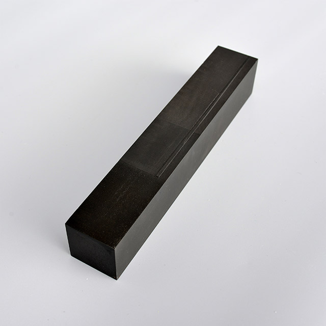
See Jungu’s flat and cylindrical thread rolling die range and flat rolling die example. For the incoming workpiece, see the blank diameter guide. Send the thread drawing, blank condition and machine limits for a tooling review.