
Replacing a Carbide Nut Die Core: Can You Reuse the Case?
A chip at the mouth of a carbide nut die is easy to see. What happened inside its steel case is harder to tell. Before ordering a replacement core, check whether the case can still locate and support it. Send the insert and case drawings together if the seat has moved, the fit is uncertain or a replacement has already failed at the same spot.
Read the seat before measuring the failed core
Identify the station and the tool revision on the drawing. Mark which end of the core faces the incoming blank. On a sectional view, point out the length that bears against the case, the shoulder that locates the core axially and any relief that deliberately leaves a gap. If an assembly has a stress ring and a separate outer case, identify both. The machine pocket diameter tells a supplier how the outside mounts. The bore that supports the core is a different measurement.
Photograph the failed die before cleaning or disassembly, where the plant's approved procedure permits it. Include a view that shows the full seat and a close-up that ties a mark to an axial position. Keep the clock position of the chip relative to a drawing datum or a mark on the case. A polished band can show where to look, but a photo cannot establish an interference fit or prove that the seat is sound.
Ask inspection to compare the empty case, where it can be measured after approved disassembly, with its released drawing. Use matching axial positions on the case bore and core outside surface. Record the instrument, measurement direction, temperature condition and actual values. One reading at the mouth can miss ovality or a change farther along the seat. If the design uses a tapered or stepped interface, identify the sections on the drawing and have the supplier review those surfaces as an assembly.
Two nominally identical cases can give different fits
For cylindrical mating surfaces measured in the same condition before assembly, diametral interference is core outside diameter minus case bore diameter. Positive values indicate interference. A negative value indicates diametral clearance. The arithmetic below is an illustration using two hypothetical bores and the same cylindrical core. The numbers are not dimensions or approval limits for a Jungu die.
| Core OD | Measured case bore | Diametral difference |
|---|---|---|
| 30.020 mm | 30.000 mm | +0.020 mm |
| 30.020 mm | 30.025 mm | −0.005 mm |
In the second example, ordering to the same outside diameter would leave a clearance at the measured section. In the first, a positive difference establishes the sign of the fit. Approval still requires the intended fit, its variation along the seat, the ring material and wall section, and the loading on the actual station. Tell the supplier if a drawing gives a radial value, since it is easy to confuse it with the diameter difference.
The General Carbide design guide explains the use of steel support to preload carbide in compression. In a separate published cold-forging study, researchers evaluated prestress in a specific input-shaft die using a tungsten carbide insert, an H13 stress ring and an outer 4140 case. This illustrates why the support parts and their materials belong in the same review. The study's design applies to its own die and loading.
Check what the measuring report calls a diameter
A report may list an average bore diameter. Ask for the individual readings if the suspect area is local. If the bore is larger in one direction than in the other at the same depth, an average can disguise the variation that matters at the chipped side. Also record the depth of each reading from the same end face. A difference between the inlet and the back of the seat can otherwise be confused with a difference between two gauges. If the result is close to the drawing limit, ask inspection to verify the method and uncertainty before deciding the case has worn.
At quotation, agree who measures and approves the reused case. If the supplier receives only a new-core drawing and a worn sample, their quotation may cover the loose insert without establishing how it will fit. If the case is sent too, specify whether you want an inspection only or a completed assembly with a record of the final working profile. Put the actual scope on the order so the two reports can be read against the same drawing revision.
When a replacement chips on the same side
Suppose a second insert chips near the entry, at about the same clock position as the first. Pull the accepted first-piece report if one exists, and put the new failed piece next to it. Mark the chip, the corresponding insert outside surface and the case seat on the same section view. Check whether the seat mark follows the same position. Also keep incoming and outgoing blanks from the affected station and check the punch and setup records for evidence of offset. The pattern is a reason to widen the inspection. It cannot establish a failed fit or a bad carbide grade on its own.
If the case bore is outside its released drawing, the locating shoulder shows damage, or the first core moved during the run, have the case and core reviewed together before the next order. If the case measures within its requirements and the seat has no unexplained marks, an insert-only quote may be reasonable. Ask the toolmaker to confirm the interface and define how the assembled working profile will be inspected. Where the drawing or measurements are missing, send the intact assembly and identify the missing information explicitly.
Agree on two inspection stages when ordering
Before assembly, the insert outside profile and the case bore establish the mating condition. After assembly, ask for inspection of the working contour and its position relative to the locating faces shown on the approved drawing. A report for the loose core answers the first question only in part. Keep both component IDs with the assembly record, then use traceable first pieces from the actual station to confirm part geometry and finish. For the blank hole handed over to tapping, use the separate pre-tapping inspection guide.
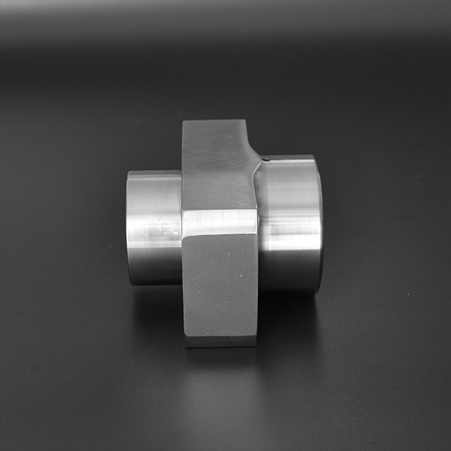
See the carbide nut forming die and the hex nut punch and die set. Send Jungu the assembly section, case readings and photos of the failed tool, with the station and material identified, for a quote on the appropriate replacement scope.